
Blockbench Overview & Tips
Community
Discord
Join the Blockbench Discord server, it is the heart of the Blockbench community! You can discuss WIP projects, share finished models, ask questions, collaborate, participate in events, or just hang out with the community.
Sketchfab
Sketchfab is a platform to publish, share, discover, buy and sell 3D, VR and AR content. Many Blockbench artists already use it to showcase their work.
You can upload models from Blockbench directly to Sketchfab, by going to "File" > "Export" > "Upload to Sketchfab". Once on Sketchfab, you can change lighting and effects and create renders or share your model. You can also build your portfolio or embed models into your website.
Sharing Models
You can easily share Blockbench models with others. Go to "File" > "Export" > "Share", copy the short link and send it to someone. They can click the link to view or edit the model in the web app.
Streamer Mode
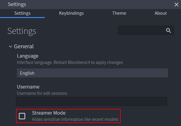
If you stream Blockbench, but don't want your audience to see other projects you worked on, enable Streamer Mode in the Settings ("File" > "Preferences" > "Settings..." > "General"). It will hide potentially sensitive information like unreleased projects.
Interface
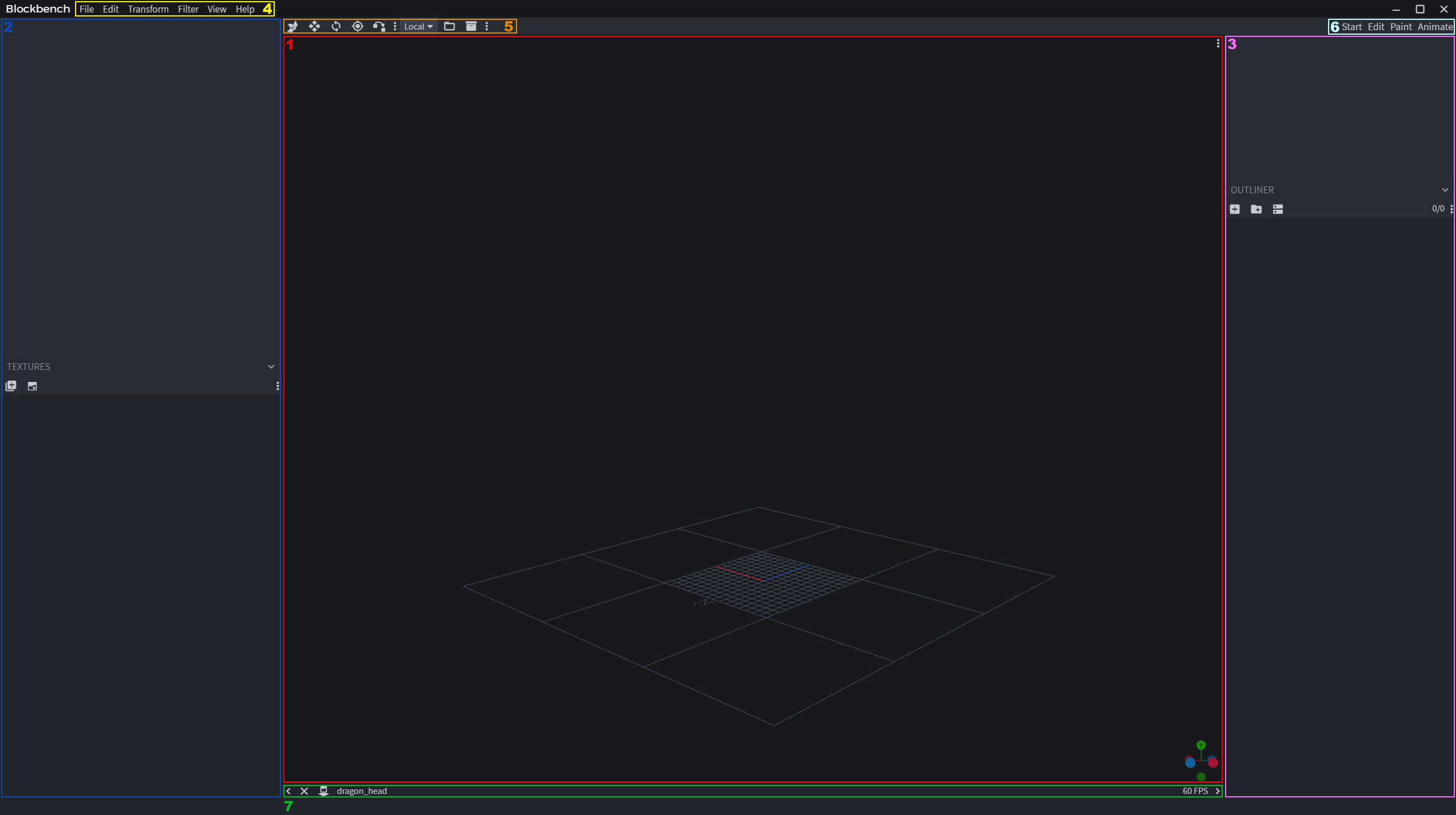
The default Blockbench interface consists of the Viewport (1, red), Left Sidebar (2, blue), Right Sidebar (3, pink), Menu Bar (4, yellow), Main Toolbar (5, orange), Mode Tabs (6, white) and Status Bar (7, green). The sidebars contain different panels (e.g. Outliner, UV Panel...) depending on the interface mode (Edit, Paint, Animate, Display).
Viewport
An axis (plural axes) is a reference line in a coordinate system that defines a dimension. In a 3D space there are three axes: X, Y and Z. In Blockbench X represents width, Y height and Z length. The origin of the coordinate system is the point of intersection between the three axes, i.e. its coordinates are (0, 0, 0). The coordinates get higher in the + direction (from the origin to where the arrow points) of each axis and lower in the - direction (from the origin to away from where the arrow points) of each axis.
The coordinate grid is made up of equally spaced intersecting lines (starting from the axes). The different grid options can be toggled in "Settings" > "Grid".
- Small Grid: single 1x1 meter pixel-accurate grid and axes
- Block Grid: additional 1x1 meter squares around the small grid
- Precise Block Grid: makes block grids pixel-accurate
- Large Box: 3x3x3 boundaries
- Block Grid Size: defines how many meters the block grid contains
- Display Mode: grid visible in Display mode
- Painting Grid: grid that covers the textured parts on the model in Paint Mode
By default the spacing equals 1 pixel unit (16 units in a meter), but it can be adjusted in "Settings" > "Snapping" > "Grid Resolution".
There are three main motions for navigating the Viewport (rotate, drag and zoom). These controls can be adjusted in Keybindings by either setting them manually or loading a keymap. Here is a list of default keymaps:
- Default (Trackpad)
- Rotate: Left Click
- Drag: Right Click
- Zoom: Shift + Left Click
- Default (Mouse)
- Rotate: Middle Click
- Drag: Shift + Middle Click
- Zoom: Ctrl + Middle Click
- Blender
- Rotate: Middle Click
- Drag: Shift + Middle Click
- Zoom: Ctrl + Middle Click
- Cinema 4D
- Rotate: Alt + Left Click
- Drag: Alt + Middle Click
- Zoom: Shift + Left Click
- Maya
- Rotate: Alt + Left Click
- Drag: Alt + Middle Click
- Zoom: Alt + Right Click
Scrolling works universally for zooming in and out in the Viewport.
Transform Gizmos are controls in the Viewport used to move, resize and rotate elements and groups. The Orbit Gizmo is a set of controls in the bottom right of the Viewport used to rotate the camera and switch to side views.
Sidebars
The Sidebars contain panels depending on the interface mode. The Outliner shows the components and hierarchy of the model and offers actions for adding, removing, moving, parenting, locking and toggling elements and groups. The rest of the panels are mode-specific and are explored in detail in the section of their respective interface mode. If you want to focus your attention only on the model itself, press the little arrow icons (in the right and left corner of the Status Bar) to toggle the Sidebars. Both Sidebars can also be quickly toggled using Ctrl+B (this keybinding can be changed in the Preferences).
Toolbars
A toolbar is a customizable bar that holds a number of actions, usually at the top of a panel. In order to customize a toolbar, click the three dots on the right side of the last tool on the bar (use "Customize" to add more tools and "Reset" to get the default set-up back). Number sliders are inputs in toolbars that support many ways of input (sliding, pressing arrows and using math expressions).
Main Toolbar
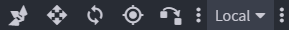
The Main Toolbar is the toolbar above the Viewport. It comes with a set of default tools dependent on the interface mode, but can be customized, like all the other toolbars. In order to customize it, click the three dots on the right side of the last tool on the bar (use "Customize" to add more tools and "Reset" to get the default set-up back).
Interface Modes
The interface modes offer a variety of tools for the different parts of the creation process.
- Edit Mode: designing and positioning models and setting up their UV mapping and bone structure
- Paint Mode: creating and editing textures
- Animate Mode: animating models (in formats that allow it)
- Display Mode: specific to the Minecraft block formats; used for defining how the model gets displayed in game (in hand, in item frames, in the inventory etc,)
Status Bar
The Status Bar contains sidebar toggle arrows and easily accessible information about the model.
- Toggle Sidebar: left and right arrow for hiding and revealing the left and right sidebar respectively
- Format Icon: icon that tells you the format of the model (hover to read)
- Model Identifier: text that states the name of the model identifier (it can be edited in "File" > "Project...")
- Available modifier keys for the current tool, if available
- Automatic warnings or errors regarding the current model
- FPS Indicator: number of frames per second displayed in Blockbench at any given moment
Sliders
The interface contains numeric sliders in various places and for various purposes, for example to adjust element transformation, to control the brush size, etc. Sliders are a combo input type that supports various methods of input:
- Sliding: Move your mouse cursor (or finger on touch) over the number in the center. Slide to the right to increase and to the left to decrease the value. Depending on input type, you can hold Shift or Control to adjust the increment.
- Arrows: Hover over the input. Two arrows pointing to the right and left appear. Press those arrows to increase and decrease the value.
- Manual Input: Click the number once to activate text editing. Enter a new numeric value. Press Enter of click elsewhere to confirm the change.
- Double Click: Double-click the number to reset the value back to 0 or the respective default value.
- Expressions: Click the number once to activate text editing. Manual input supports math expressions using MolangJS syntax.
The advantage of this is that the expression will be applied to each instance separately. For example, you can enter
math.random(-30, 30)into the rotation value of your selected cubes. This will randomize the rotation for all cubes, and each cube will end up with a different rotation. You can prefix your expression with+,+-,*or/to add to, subtract from, multiply, or divide by the previous value respectively. For example, typing*2into a size input field will double the size value of all selected elements. You can also usevalornin your expression as a placeholder for the previous value.
General
Terminology
Here is a list of useful words and their definitions to easily communicate what you are working on or having trouble with.
- Group: organizational structure that contains elements and other groups
- Bone: group that can be rotated (i.e. in a format that supports group rotation)
- Element: anything in the outliner that is not a group (e.g. cube, locator, etc.)
- Cube: element of the geometry (refers to all cuboids regardless of dimensions, not just geometric cubes)
- Plane: special type of cube with only 2 faces (due to one of the dimensions of the cube being 0)
- Locator: dimensionless element in the model that can be used as a reference point (e.g. to position particles)
Keybindings
Keybindings (keyboard shortcuts) are one of the main ways to speed up your workflow. To learn them, hover over actions (the keybinding will appear next to the label), open the menus or search them in "Preferences" > "Keybindings". If there is no keybinding for an action, you can in most cases define one in "Preferences" > "Keybindings". Default keybindings can also be changed there.
Selecting Elements
Elements can be selected in the Viewport and Outliner by left-clicking.
- Hold Ctrl while left-clicking to select multiple elements
- Hold Shift in the Outliner to select a range of elements
- Hold Shift in the Viewport to select the entire group
- Hold Ctrl while left-clicking on a UV island in the UV panel to select elements based on their UV map
- Select all elements using Ctrl+A
Screenshots
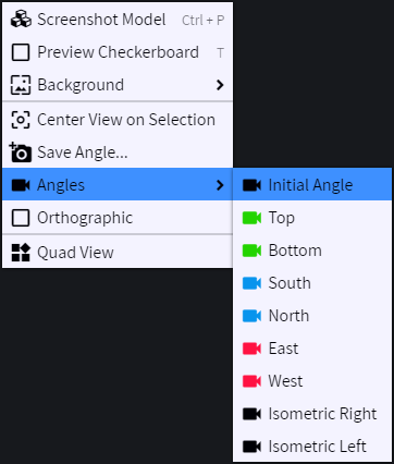
Press Ctrl + P to capture a screenshot (the keybinding can be changed in the Preferences). Alternatively, open the Preview menu (right click in the Viewport or click the 3 dots in the top right corner of the Viewport) and select "Screenshot Model". In the Preview menu, you can also select one of the preset angles, or create, save and load your own before taking the screenshot.
Background Image
You can load background images into Blockbench. A background can be helpful to customize the interface, to load a reference image or to be used as a blueprint. Open the Preview menu (right click in the Viewport or click the 3 dots in the top right corner of the Viewport) to load and edit background images.
View Mode
Press Z to switch between Textured, Solid and Wireframe Mode. The Solid Mode enables you to view the shape of the model without the texture. The Wireframe Mode only shows the shape outlines, allowing you to see through the model and align cubes and pivot points more easily.
Backups
Losing progress is rarely a concern with Blockbench because it creates automatic backups once every 10 minutes by default (you can adjust the interval length in the Settings). Click "Help" > "Open Backup Folder" and locate the right backup file.
Progressive Web App
You can install Blockbench as a Progressive Web App. This is an in-between of the desktop app and the web app and is particularly useful on Phones and Tablets. PWAs launch in full screen and work offline! Find installation instructions on the Download page.
Edit Mode
Panels
The UV Panel consists of the UV Editor, texture size, Full View (a dialog pops up with a larger version of the UV Editor) and UV Window buttons (a dialog pops up that displays all faces next to each other). In the Box UV mode, there is also a UV Overlay toggle (to show/hide all UV maps at once) and a Mirror UV action (to mirror the UV on the X axis). The UV Editor comes with two sliders, for horizontal and vertical position. In the Per-Face UV mode, there is a different tab for each face's UV in the UV Editor. The UV Editor also comes with four sliders, two for position and two for scale.
The Textures Panel contains a list of all imported textures and two actions - Import Texture and Create Texture.
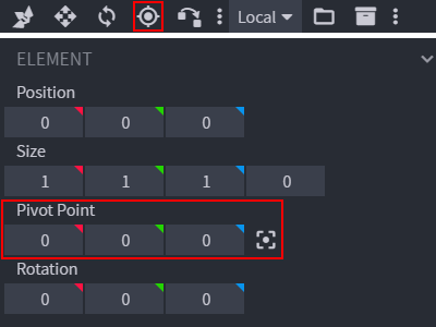
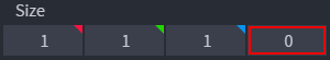
The Element Panel contains toolbars with sets of sliders for Position, Size, Pivot Point and Rotation. Next to the Size sliders, there is also the Inflate slider and, next to the Pivot Point sliders, there is the Center Pivot action.
Tools & Actions
The Main Toolbar in Edit Mode offers the following tools by default:
- Move: Translate elements and bones.
- Resize: Change the size of elements.
- Rotate: Rotate elements and bones.
- Pivot Tool: Move pivot points (centers of rotation) for cubes and bones.
- Vertex Snap: Connect two cubes by moving or scaling them for one vertex (from each cube) to reach the other.
Pressing Space or double-clicking switches between the alternative tools (Move and Resize; Rotate and Pivot Tool). This keybinding can be changed in the Preferences.
Transform spaces (Global, Bone, Local) define how elements/bones and their pivot points are going to be translated depending on their absolute and relative position and rotation.
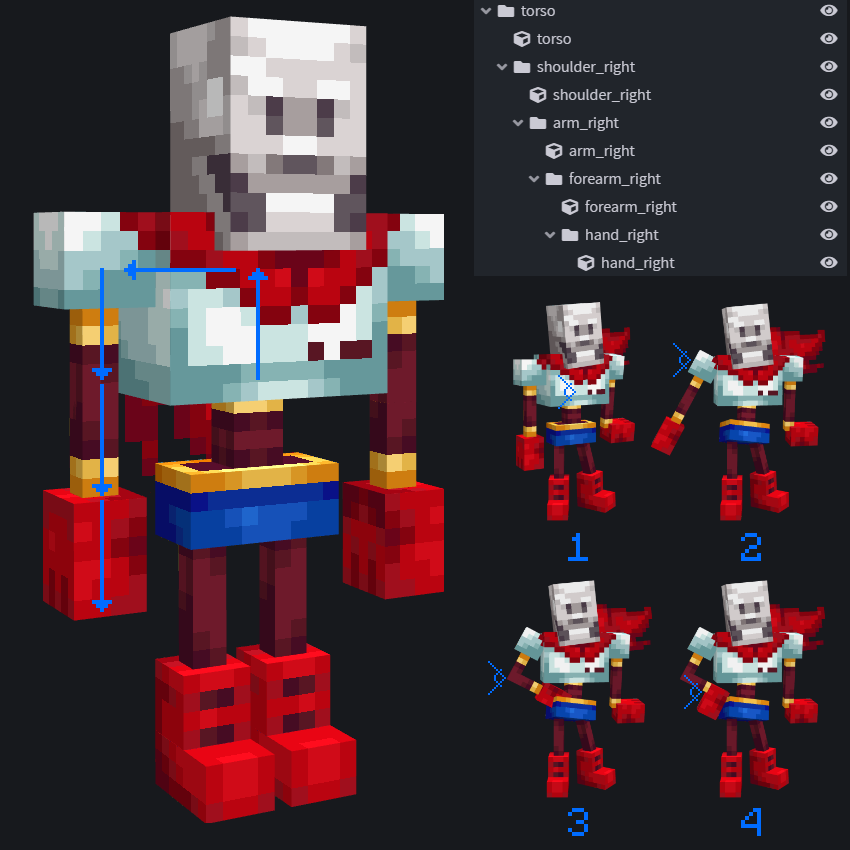
Bones & Parenting
Parenting is the process of attaching bones to each other in a hierarchical order. Child bones can be manipulated on their own, but they are also forced to follow the parent bones. It is crucial for posing and animation. The best bone structure is one that allows for the most intuitive bone manipulation (e.g. if the torso moves, the arms should follow). Parenting should be done outward, from proximal bones (closer to the center of the body) to distal bones (away from the body). Along with parenting, setting the pivot points correctly is the most important part of creating the bone structure. Posing and animating can also be done outward (as seen in the image below marked with numbers 1-4). For a cleaner workflow, bones should have a consistent naming convention.
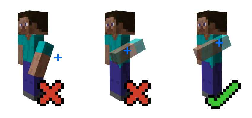
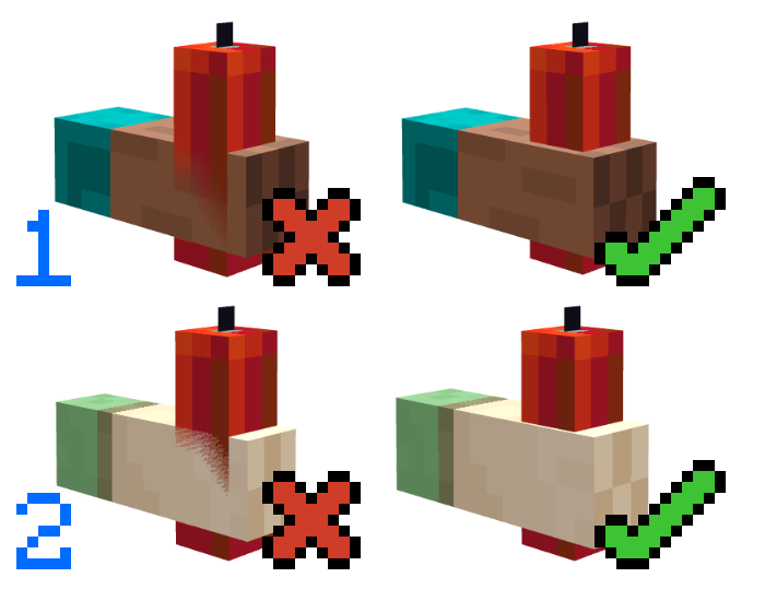
Pivot Points
A pivot point is the center of rotation of a bone. It should not be placed randomly (left-most example in the image below) because that can lead to issues with animation and/or later edits of the model. The center of rotation is usually not supposed to be at the center of geometry (middle example in the image below). As a general rule, the pivot point should be at the center of the joint (point of attachment between two bones; right-most example in the image below).
The pivot point can be set in the viewport using the Pivot Tool (found in the Main Toolbar) or in the sidebar using sliders (found in the Element panel). The pivot point can also be centered to the selection using the button next to the Pivot Point sliders.
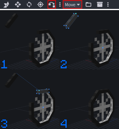
Vertex Snap
In order to fix cracks and slight imperfections in the position of certain elements, you can use Blockbench’s Vertex Snap tool. This is a method of moving vertices of one element to coincide exactly with the vertices of another element. You should select "Vertex Snap" in the Main Toolbar and select "Move" or "Scale" in the drop-down, depending on the action you wish to perform.
- A cube isn't positioned correctly on the model.
- Select the cube you are trying to move (or scale). Click on one of its vertices that needs to be snapped.
- Select the cube that you are snapping to and click on one of its vertices (where you're directing vertex of the first cube). A line will appear between the two vertices on hover.
- The cube is snapped into the correct position.
Vertex Snap also works as a tape measure. Simply select one vertex and hover over another one. You will see the distance between the two vertices in the status bar.
Inflation & Deflation
The Inflate feature enables you to scale cubes by the same number on all axes (in all directions), while keeping the UV mapping intact regardless of the UV mode (per-face or box UV). The Inflate slider can be found next to the Size sliders in the Element panel.
Z-Fighting
The Z-buffer is a technology of managing the image depth coordinates in 3D graphics, which helps distinguish objects that are rendered from those hidden behind them. Z-fighting is an artifact that occurs due to coplanar cubes (or cubes that are almost coplanar) sharing the same Z-value. It results in fragments of both faces being rendered. To avoid it, the cubes can be moved away from the conflict if the geometry allows it (1) or one of them can be inflated/deflated (2).
Transform
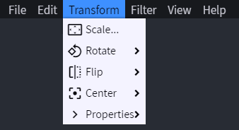
The Rotate feature enables you to turn the selected elements by 90° in either direction on any axis. In per-face UV mapping, the mapping of the faces stays intact after performing the rotate action. Box UV cannot preserve the mapping, so it is usually better to use bones for rotating a larger quantity of elements together.
In many cases, there are shapes on the model that need to be symmetrical. Using the Flip feature, you can make those elements/bones only on one side and mirror them to the other, instead of doing everything manually. It works on all three axis, but X is likely to be used the most. It will also rename the bone for you from left to right and vice versa (e.g. the duplicate is called leg_right2, but when you flip it, the name will change to leg_left).
Models need to be aligned on the coordinate grid (in most cases centered on the X and Z axis). To do this reliably, use the Center feature for the axis where you wish to center your model.
Paint Mode
Panels
The UV Panel contains the same features as in Edit Mode. However, in Paint Mode the UV Editor can be used for painting, instead of setting UV mapping.
The Textures Panel contains a list of all imported textures and two actions - Import Texture and Create Texture.
The Color Panel contains the Color Bar (with the selected color and its HEX value displayed, as well as Color History). Below it, there are three tabs: Picker (which shows the HSV color picker), Palette (which shows the palette with options to import, export, generate, sort and load a palette) and Both (which shows both the HSV color picker and the palette at the same time). The HSV Color Picker, aside from the hue ribbon and saturation/value coordinate system, contains the HSV sliders and two actions - Add To Palette and Pick Screen Color.
Tools & Actions

Tools that can be found on the Main Toolbar in Paint Mode:
- Paint Brush: Paint on surfaces of the model or in the UV Editor.
- Paint Bucket: Fill (depending on the Fill Mode) faces, cubes or connected or separate areas of the texture with a single color.
- Eraser: Replace pixels on the texture with transparency.
- Color Picker: Select colors from the existing parts of the texture. The color picker also works on background images. That way you can directly pick colors from your reference image instead of creating a new palette. Holding Alt temporarily selects the color picker for the duration of holding Alt (and switches back after you stop holding Alt). This is a great way to optimize your painting workflow. Pressing Space switches to the Color Picker.
- Draw Shape: Draw simple shapes (full/hollow rectangle, full/hollow ellipse).
- Gradient Tool: Create a color gradient.
- Copy Paste Tool: Select, copy/cut and paste portions of the texture.
Size, opacity (lack of transparency) and softness (gradual transparency around the edges) can be defined for some of the tools. Hold Shift to draw a line with the Paint Brush or Eraser.
Actions to speed up the texturing process:
- Mirror Painting: Automatically copy all edits to the opposite side of the model according to the X axis.
- Lock Alpha Channel: Disable painting on transparent parts of the texture.
- Painting Grid: Toggle the pixel grid that covers the textured parts of the model.
Texture Preview
You can use an external image editor and use Blockbench for live 3D preview. For regular pixel art textures, you can directly use Blockbench's pixel art tools without the need for external software.
Animate Mode
Panels
The Animations Panel contains a list of all animations, a slider for the length of each animation and actions for creating and importing animations. You can select an animation in the list by left-clicking it, open Animation Menus by right-clicking and open Animation Properties by double-clicking.
The Keyframe Panel contains the timecode slider and interpolation drop-down. It also states whether it's a rotation, position or scale keyframe and contains text inputs for each axis.
The Bone Panel is similar to the Element Panel in Edit Mode. However, it only allows for adjusting bone properties because elemenets cannot be animated.
The Timeline gives an overview of the animation and its properties. It consists of the Header and the Main View (which can be either Keyframe View or Graph Editor View). The Keyframe View allows you to set and display keyframes of all active channels at once. The Graph Editor View allows you to adjust animation curves in a selected channel.
Timeline Header

In the Timeline Header there are several actions for adjusting the Timeline and previewing the animation.
- Toggle Graph Editor: switch between Keyframe View and Graph Editor View
- Filter Channels: toggle visibility of channel types and empty channels
- Clear Timeline: hide all unselected bones from the Timeline
- Animate Effects: add channels for animating particles, sounds and instructions
- Set Marker: add/remove marker
- Playback Speed: slider that dictates the speed of the animation in percentage
- Previous/Next Keyframe: transport controls to jump through the animation
- Play Animation: start/stop selected animation
Timeline Main View
The Time Ruler is the strip (at the top of the Main View) that graphically represents time using equally spaced markings (units of time). The blue square bracket on the Time Ruler indicates the end of the animation.
The Playhead is the blue vertical line with an arrow at the top that shows the current time in the animation. When scrubbing through the Timeline, the Playhead snaps to valid frame times by default. Hold Ctrl to disable snapping and move it smoothly.
The Timecode (top left corner) displays the current position of the Playhead. You can type to edit the Timecode to jump to a specific time in the animation.
Markers are indicators on the Time Ruler that can be used to denote significant points in the animation and let you quickly jump to them. On right click they can be colored differently or deleted.
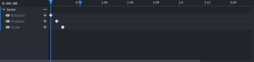
On the far left, below the Timecode, there is a list of all bones and their channels. Timeline Tracks are rows (below the Time Ruler) where keyframes for each channel are defined (each track belongs to one channel).
Keyframes are the start and end points of any change in the animation. They are represented by diamond shapes (for linear interpolation) and circles (for smooth interpolation) on the Timeline Track. A group of keyframes can be selected by left-clicking and dragging. You can organize your timeline by color-coding keyframes. Select a keyframe (or a group of keyframes) and right click to choose a marker color.
The Scrollbar at the bottom of the panel lets you pan the Main View.
Display Mode
Actions
"Copy" and "Paste" actions allow you to transfer the values from one Slot to another. The "Apply Preset" action offers a list of default values for different purposes (e.g. items, blocks...). The "New Preset" action is used for adding your own presets (defined values for one or more slots) to the list.
Slots
The rotation, translation and scale of the model can be defined separately for each slot.
- Thirdperson (left and right): outside of the first-person view (i.e. to other players or when switching views using F5)
- Firstperson (left and right): what the handheld model looks like to the player holding it, while in first-person view
- Head: when placed on the entity's head
- Ground: when dropped on the ground (floating above the ground)
- Frame: in an item frame
- GUI: in the GUI (graphical user interface; e.g. in the inventory slot)
The GUI display offers two lighting options: Side Light and Front Light. Side light is intended for models shown at an angle (like blocks in vanilla Minecraft). Front light is intended for models directly facing the screen/player. Make sure to use the correct one in order to avoid your models standing out from the rest of the inventory.
Reference Model
There are different display references for some slots. They can be switched between based on the purpose of the model. For example, the Thirdperson and Head slots offer displaying the model on the player, zombie, baby zombie, armor stand and small armor stand.